BLDC Robot Actuator
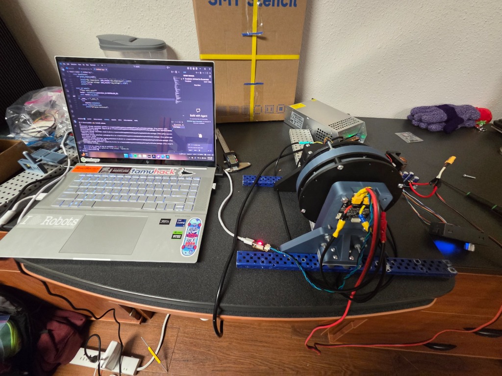
At a Glance
| Goal | Convert a $30 hoverboard hub motor into a high-torque, closed-loop robotic actuator |
| Hardware | 400W BLDC motor, mjbots moteus r4.11, AS5047P absolute encoder, Arduino thermal monitor, 35V bench supply |
| What I Built | A custom locked-rotor test fixture with wiring harness and sensor stack, plus a multi-sensor async Python telemetry pipeline over CAN-FD and a real-time haptic feedback detent controller |
| Key Result | Mapped full motor parameters (30 pole pairs, 0.265 Ohm, 24.18 KV) and diagnosed a permanent 20% torque loss caused by NdFeB magnet demagnetization under high stall current |
The Core Idea
Hoverboard motors are one of the best-kept secrets in robotics. For roughly $20-40, you get a large-diameter BLDC motor with an impressive torque output, delivering a torque-to-price ratio that leaves conventional servo motors in the dust. My goal was simple: turn these commodity motors into viable, closed-loop robotic actuators. This writeup covers the full stack, from winding physics to async Python architecture.
Here is how I did it.
Choosing the Right Motor Controller
The first challenge was finding a motor controller capable of running Field-Oriented Control (FOC) on a large, multi-pole hoverboard motor. After evaluating several options, I landed on the Moteus r4.11: a compact, high-performance brushless motor controller that natively supports CAN FD communication and has excellent Python tooling for scripting and data collection.
For position sensing and commutation, I chose the AS5047P absolute magnetic encoder. Unlike incremental encoders, it provides an absolute position reading on startup, which is critical for reliable homing and multi-turn tracking in a robotic joint.
The Hardware Stack
I fabricated a custom locked-rotor test fixture and wired the full sensor stack, including motor phase leads, encoder SPI lines, thermistor cabling, and CAN-FD termination.
| Component | Specs |
|---|---|
| Hoverboard hub motor | 400W, 36V, BLDC, 30 pole pairs |
| mjbots moteus r4.11 | CAN-FD FOC controller, 54V/100A peak |
| AS5047P magnetic encoder | 14-bit resolution, SPI, 200Hz observer |
| Arduino + NTC thermistor | External motor winding temperature |
| 35V regulated bench supply | Stiff bus voltage for repeatable tests |
Motor Physics: What the Calibration Reveals
Before writing a single line of test code, you need to understand what you are driving. I ran the moteus automated calibration pipeline, which performs a sequence of controlled electrical measurements to fully characterize the motor from first principles. No datasheet required.
How Each Parameter is Measured
Winding Resistance (0.265 Ohm): The calibrator locks the rotor stationary and injects a known DC voltage across two motor phases, then measures the resulting steady-state current. With back-EMF eliminated because the rotor is not spinning, R = V / I gives direct phase resistance. This value is critical for computing the maximum thermally-sustainable current and predicting copper losses under load.
Phase Inductance (387 uH): The calibrator sweeps a small AC current signal across the winding at known frequencies and measures the phase lag between voltage and current. The reactance X_L = 2*pi*f*L gives inductance directly. This value determines the current loop bandwidth. The moteus auto-tunes its current loop PI gains directly from this measurement:
pid_dq_kp: 0.487       # proportional gain
pid_dq_ki: 333.07      # integral gain
torque_bandwidth: 200 Hz
KV (24.18 RPM/V): With the motor spinning freely at a known speed driven open-loop, the calibrator reads the back-EMF amplitude on the undriven phase. Since BEMF = KV * omega, dividing out the speed gives the torque constant Kt = 1/KV, which is the fundamental ratio between current and torque output.
Pole Pair Mapping (30 pairs, 64-entry offset table): The calibrator slowly rotates the rotor through one full mechanical revolution while commanding known electrical angles and recording the encoder reading at each step. This maps every electrical cycle to physical rotor position and detects non-uniformities in magnet spacing or flux. The resulting 64-entry offset table is applied in real-time at every commutation step, compensating for manufacturing tolerances that would otherwise produce torque ripple at the pole-pair frequency.
Final calibration results:
| Parameter | Measured Value |
|---|---|
| Pole pairs | 30 |
| Winding resistance | 0.265 Ohm |
| Phase inductance | 387 uH |
| KV | 24.18 RPM/V |
| Current loop bandwidth | 200 Hz |
| Current quality factor | 74.69% |
The 30-pole-pair count is significant. Hoverboard hub motors use a high pole count to produce high torque at low RPM without a gearbox, running direct drive. This means electrical commutation happens 30x per mechanical revolution, which demands a fast control loop. The moteus handles this with a 32kHz PWM switching frequency and a dedicated Cortex-M4 + FPGA signal chain.
CAN-FD Communication
The moteus controller communicates over CAN-FD (Flexible Data-Rate CAN), not standard CAN. CAN-FD allows data payloads up to 64 bytes versus 8 bytes on classic CAN, and bit rates up to 8 Mbit/s on the data phase. For real-time motor control this matters because you can fit a full position, velocity, torque, and telemetry command-response pair in a single frame without fragmentation.
The moteus protocol uses a compact binary register map. Each register has a known address:
REG_POSITION  = 0x001
REG_VELOCITY  = 0x002
REG_TORQUE    = 0x003
REG_Q_CURRENT = 0x005
REG_FAULT     = 0x00b
REG_VOLTAGE   = 0x00d
REG_TEMP      = 0x00e   # Controller board temperature
Commands and queries are transactional. A single set_position() call sends a command frame and receives a reply containing the requested telemetry in the same round-trip. My control loop achieves 50Hz closed-loop updates over this interface using the moteus Python SDK, running inside a Python asyncio event loop.
The AS5047P Magnetic Encoder
Position feedback is provided by an AS5047P absolute magnetic rotary encoder. It is a 14-bit (16,384 counts/rev) Hall-effect sensor that reads from a diametrically magnetized magnet on the rotor shaft over SPI. Unlike optical encoders, it has no moving parts and is immune to contamination, making it well suited for motor applications.
The moteus runs a dedicated encoder observer tuned to 200Hz bandwidth:
encoder_filter_kp: 1013.4
encoder_filter_ki: 256753.5
This observer fuses raw encoder counts with the motor dynamic model to produce a smooth, low-latency velocity estimate even at high pole counts. This is critical for stable current control at 30 pole pairs, since phase lag in the velocity estimate would corrupt the FOC commutation angle and produce instability.
The calibration process maps encoder position to electrical angle across all 30 pole pairs, producing a lookup table that compensates for magnet placement tolerances and encoder eccentricity.
Locked-Rotor Torque Test
The core test is a locked-rotor (stall) torque characterization. The motor is mechanically clamped, and torque is commanded via a linear ramp from 0 to 15 Nm over 10 seconds, then held at maximum for 2 seconds. The key control configuration is pure feedforward torque mode:
await self.c.set_position(
    position=math.nan,    # No position target
    velocity=0.0,
    kp_scale=0.0,         # PID disabled
    kd_scale=0.0,
    feedforward_torque=cmd_torque,
    maximum_torque=MAX_TEST_TORQUE + 1.0,
    query=True
)
Setting kp_scale=0 and kd_scale=0 bypasses the position PID entirely. The controller becomes a pure current amplifier. Commanded torque maps directly to q-axis current via Iq = T / Kt, giving a direct measurement of the motor current-to-torque conversion.
Multi-Layer Safety Interlock System
Three independent abort conditions protect hardware during high-current stall testing:
1. Slip guard:       abort if |velocity| > 1.0 rev/s   (rotor not locked)
2. Controller temp:  abort if moteus board > 60 C       (register 0x00e)
3. Motor temp:       abort if winding sensor > 60 C     (Arduino serial)
If any condition triggers, set_stop() is called immediately and the partial dataset is flushed to disk.
Multi-Sensor Fusion: Arduino + moteus Telemetry
The moteus reports its own controller board temperature, but that tells you nothing about motor winding health. The windings are what actually fails first under sustained stall current. Winding temperature is a direct proxy for insulation life and magnet integrity.
I added an Arduino with an NTC thermistor mounted to the motor casing and fused both temperature channels into the telemetry stream. The challenge was that the main control loop runs async at 50Hz, so blocking serial reads would stall the entire loop. The solution is a background reader thread using a producer-consumer pattern:
class ArduinoTempReader:
    def __init__(self, port, baud):
        self.latest_temp = None
        self._stop = threading.Event()
        self._ser = serial.Serial(port, baud, timeout=1)
        self._thread = threading.Thread(target=self._read_loop, daemon=True)
        self._thread.start()

    def _read_loop(self):
        while not self._stop.is_set():
            raw = self._ser.readline().decode('utf-8', errors='replace').strip()
            value_str = raw.split(':')[-1].strip().split()[0]
            self.latest_temp = float(value_str)   # always fresh, non-blocking
The async control loop samples arduino.latest_temp each cycle with zero latency added to the critical path. The live console output shows both thermal channels simultaneously:
[HOLD] Cmd: 15.00 Nm | Meas: 6.86 Nm | Vel: 0.00 r/s | V: 35.00V | Ctrl: 43.0C | Motor: 40.0C
Both channels are timestamped and written to CSV at 50Hz for post-hoc thermal analysis.
Speed Sweep and Torque-Speed Curve
speed_test.py sweeps the motor from 1 to 40 rev/s in 2 rev/s increments, holding each step for 5 seconds while logging velocity tracking error, torque, and bus voltage. An automatic saturation detector aborts the sweep when the motor can no longer follow the commanded velocity:
if step_data['max_velocity_achieved'] < velocity * 0.5 and velocity > 5.0:
    print("Physical limit reached. Aborting sweep.")
    break
With KV = 24.18 RPM/V and a 35V bus, theoretical no-load max speed is approximately 846 RPM (14.1 rev/s). The sweep quantifies how much the real speed falls short of this ideal due to resistance losses, frictional loading, and controller current limits.
Haptic Feedback Mode
As a separate application on the same hardware stack, I implemented a haptic detent knob. The motor simulates the feel of a precision mechanical encoder at 100Hz. The control law runs a real-time virtual spring, damper, and friction model:
spring_torque   = STIFFNESS * position_error        # restoring force to detent
damping_torque  = -DAMPING * current_vel            # velocity-proportional drag
friction_torque = -copysign(FRICTION, current_vel)  # coulomb friction
total_torque    = spring_torque + damping_torque + friction_torque
This demonstrates closing a real-time feedback loop at the torque level, which is the same technique used in force-controlled exoskeletons, haptic surgical tools, and collaborative robot arms.
Data Pipeline and Root Cause Analysis
All test runs auto-save timestamped CSVs. plot_results.py generates matplotlib figures with dual y-axes, estimated current overlays using the measured Kt, and peak annotations.
During testing, I discovered a revealing anomaly. The first locked-rotor run measured 8.59 Nm, but every subsequent run stabilized at 6.84 Nm, a permanent 20% reduction. I systematically eliminated causes:
- Supply voltage: Rock-solid at 35.00V across all runs. Ruled out.
- Velocity creep (back-EMF): Velocity read 0.00 r/s in later runs. Ruled out.
- Thermal winding resistance rise: This would cause gradual drift, not a one-time step change.
The data pointed to partial permanent magnet demagnetization. The second test pushed motor surface temperature to 64C, and internal winding temperature likely reached 80 to 100C. At those temperatures, the coercivity of NdFeB magnets can drop below the demagnetizing field generated by high stall current, causing irreversible flux loss. The result is a permanently reduced torque constant Kt, consistent with the one-time step decrease in measured torque that did not recover with cooling.
What I Would Do Differently
The demagnetization event was avoidable. In future tests I would impose a hard winding temperature abort at 55C rather than 60C, leaving a wider margin before the magnet flux loss threshold. I would also add a direct Kt measurement at the start of every test run by computing torque per amp from the telemetry data, so any degradation is caught and logged automatically rather than appearing as an unexplained anomaly in post-processing.
Skills Demonstrated
| Area | What Was Done |
|---|---|
| Motor Control | FOC feedforward torque mode, back-EMF analysis, Kt measurement, demagnetization diagnosis |
| Embedded Systems | CAN-FD protocol, SPI encoder integration, AS5047P observer tuning, Arduino serial peripherals |
| Software Architecture | Python asyncio + threading, producer-consumer pattern, 50Hz real-time telemetry loop |
| Signal Processing | Encoder observer filter design (Kp=1013, Ki=256K), velocity estimation from 14-bit position |
| Test Engineering | Multi-layer safety interlocks, automated timestamped logging, multi-run repeatability analysis |
| Root Cause Analysis | Data-driven failure hypothesis from telemetry signatures |